What is etherforth
Let's start by clearly stating that etherforth is an experimental programming environment, suitable for exploring GA144 multi-computer chips. It is a system that can be used to develop demo applications and hobby projects. It should not be considered a professional programming tool as it is a hobby project of mine itself. If you wish to work with GreenArrays' chips on a professional level, I'd recommend using GreenArrays' arrayForth 3 development environment. However, if your intention is to experiment with GA144 chips and have a lot of fun, etherforth may be the right way to go.
Another thing to be clarified is meaning of etherforth name. As said above, it is a programming environment. It is name of a programming language too. And it is also name of a program running on PC under colorForth that is used to build etherforth image. I'll try to make sure it's always clear from the context which one I'm talking about.
This page gives an overview of principles etherforth is based on, and provides a brief description of all system parts. Information given here is based on the original Chuck's text. It has been updated, modified, expanded, and is presented below with Chuck's permission. During development I have changed some system features so the explanations given here may differ slightly from the original.
Ether
First, etherforth is based on ether; code loaded after reset into all nodes of GA144 chip that is used to route messages between nodes. In host chip it enables bootloading (either from a PC via USB or from serial flash memory) and communication between system modules; in target chip it is used to deliver compiled code to target nodes, as well as to send messages between application modules. When code is delivered to a target node it overwrites ether in node's RAM. However, if port execution is still possible, we can load ether back into that node.
When booting a chip, we first need a boot code to be executed in the boot node (node 708 when using async line for booting from a PC; 705 when booting from onboard serial flash). This boot code then loads ether code into a neighbor node via a shared port. Then that neighbor is given a packet with instructions to replicate itself along some path. Then other paths until the chip is fully populated. So ether exists in 143 computers, with the exception of the boot node.
Ether messages
Each ether message is a packet with a 4-word header and payload:
- header
- focus
- address
- path
- counts
- payload (with optional link as the first word)
Focus
All computers reset to waiting for instructions from a neighbor. This is usually termed a multiport execute, regardless whether a node has 4, 3 or only 2 ports. After loading ether, computers return to the multiport execute.
It is prudent when receiving instructions to switch from multiport execute to a focused 1-port execute. Otherwise confusing input may come from other ports. But more importantly, when replying it avoids a broadcast that can confuse or hang neighbors who are likely hoping for instructions from you.
So the first instruction in an ether packet is a focus - a call instruction to the port from which the packet comes. With the program counter set to this port, instructions will be executed only from it and data fetches/stores using @p and !p will go through it.
Address
This is another call, this time to code in RAM. Ether code has 2 entry points: one to transfer the payload, another to replicate ether code and then transfer the payload. This call has another function. It pushes the previous program counter (port address) to the return stack. From there it can be moved to an address register (pop a!) to receive additional data. And send reply.
Path
This is a word that describes the route the message is to follow. Path has three 6-bit fields, each with the format:
| n | n | n | n | d | d |
- nnnn
- length - 4 bits, 0-15 nodes
- dd
- direction - 2 bits
A path consists of 3 segments:
| 0 | 3 | 3 | 3 | 3 | 3 | 2 | 2 | 2 | 2 | 2 | 2 | 1 | 1 | 1 | 1 | 1 | 1 |
Segments 1 and 2 have maximum length 15; segment 3 can only go 7 (so the sign bit doesn't propagate with right shift). Thus a path might say: go down 3 nodes; then left 10 nodes; then down 2 nodes (3 d 10 l 2 d). A path starts in the neighbor of the sending node, and ends right before the destination node. Thus, it does not include sending and destination nodes.
Directions are coded
- right is 0 (r)
- left is 1 (l)
- up is 2 (u)
- down is 3 (d)
These are physical directions on the chip. As distinct from the ports names which permute from node to node.
In each step the length field of the current segment is decremented. When it becomes 0, this segment has finished, and we move to the next one. When the last length is zero, the destination has been reached. The destination node is the neighbor in the current direction.
The last run can have 0 length. That means to turn in that direction but not move. However, this turn cannot be to the right: 0 r is indistinguishable from 0, which means end of path.
Counts
The counts word has the following format:
| 0 | r | r | r | r | r | r | r | r | r | p | p | p | p | p | p | p | p |
- 0
- in msb so the sign bit doesn't propagate with right shift
- rrrrrrrrr
- reply - 9 bits 0-511 words
- pppppppp
- payload - 8 bits 1-256 words
A payload of 0 indicates 1 word. A reply of 0 indicates no reply.
Link
If the route runs into a link node (a node that links to another chip) there needs to be another path to follow in the next chip. This would be the first word in the payload and the header is rearranged by the link node. Normally, you don't need to be concerned with link code. Since etherforth deliveres compiled code directly to the target chip, link is added to ether message implicitly.
Payload
Payload contains instructions to be executed. Focus and address are also instructions; path and counts are data, read by ether code. Payload starts with instructions that explain what to do with following data. Commonly, store into RAM. After that data is exhausted, more instructions may follow. For example, initialize registers and stack.
Payload has a maximum length of 256 words. This is adequate to fill the 64 words of destination RAM and execute initialization code in node's port. Reply has a maximum length of 511 words. This is sufficient to fill a screen with a target node's memory and stack dump when examining the node with peer command.
There must be a payload of at least 1 word. That might just be a return to multiport execute.
Symbols, tags, characters, tokens
Similarly to colorForth, etherforth source code is pre-parsed. However, unlike in colorForth, where source code is encoded using Shannon-coded characters, etherforth uses 6-bit symbols. A symbol may be tag, character, or token. A word is a string of 6‑bit characters preceeded by a 6‑bit tag, and is terminated by the next tag. A word may be a word proper, such as a name of definition, or a number, decimal or hex, still a string of characters (different from colorForth that stored numbers in binary). Decimal numbers may start with a minus sign.
Tags
Tags have following format:
| 1 | 1 | n | n | n | n |
- 11
- indicates the symbol is a tag
- nnnn
- code of the tag, 0 - 15
Tags define what color and form is used when symbols that follow the tag are being displayed. It also indicates how the following symbols are to be processed with compiler. There are also tags used for source code formating purpose.
Table below shows 16 tags with their corresponding function and color.
| hex | tag | color | hex | tag | color |
|---|---|---|---|---|---|
| 30 | token | 38 | dec | ||
| 31 | token | 39 | eol | ||
| 32 | char | 3A | space | ||
| 33 | hex | 3B | cursor | ||
| 34 | hex | 3C | eob | none | |
| 35 | char | 3D | char | ||
| 36 | dec | 3E | char | ||
| 37 | char | 3F | char |
It may seem that there are more colors than in colorForth; that's correct. The main difference is that yellow and green words (defined names) have slightly modified shades; peach instead of yellow, and mint green instead of plain green. Similarly to colorForth, numbers expressed in base 16 are displayed as darker shades of yellow (brown) and green (pine). In colorForth, editor limits available symbols based on currently selected color. For instance, when entering decimal numbers it is not possible to type letters. When entering hex numbers only letters a to f are accessible. Editor in etherforth has no such safeguard mechanism so using different colors helps spot errors quickly.
Function of different colors during compilation is the same as in colorForth. Red words are definitions, green are compiled, and yellow executed. The rest is ignored and can be used for text formating purposes or as comments.
Symbol eol (end-of-line) is displayed as a dark blue comma. It is displayed automatically to indicate where the end of line is located. Space symbol (represented by a blue dot in colorForth) is displayed as a blank. Symbol eob (end-of-block) is not displayed at all and thus has no associated color. Cursor  is a special symbol that is not part of etherforth character set but it has color defined as if it was a symbol. Your application code can display arbitrary text on the screen using all available colors except for dark blue reserved for eol comma symbol.
Characters and tokens
Symbols not having two most significant bits set are either characters or tokens. Whether a symbol is displayed as character or token depends on the tag preceding the word; tokens are preceded by tags 30 and 31, other tags indicate characters. Table below shows whole etherforth character set and corresponding tokens.
| hex | char | token | hex | char | token | hex | char | token | hex | char | token |
|---|---|---|---|---|---|---|---|---|---|---|---|
| 00 | 0 | ; | 0C | c | !p | 18 | o | dup | 24 | * | io |
| 01 | 1 | ex | 0D | d | !+ | 19 | p | pop | 25 | / | zif |
| 02 | 2 | end | 0E | e | !b | 1A | q | over | 26 | @ | till |
| 03 | 3 | begin | 0F | f | ! | 1B | r | a | 27 | ! | -till |
| 04 | 4 | unext | 10 | g | +* | 1C | s | . | 28 | . | for |
| 05 | 5 | next | 11 | h | 2* | 1D | t | push | 29 | , | -when |
| 06 | 6 | if | 12 | i | 2/ | 1E | u | b! | 2A | ; | left |
| 07 | 7 | -if | 13 | j | - | 1F | v | a! | 2B | ' | right |
| 08 | 8 | @p | 15 | k | + | 20 | w | then | 2C | # | io |
| 09 | 9 | @+ | 16 | l | and | 21 | x | else | 2D | - | down |
| 0A | a | @b | 17 | m | or | 22 | y | ahead | 2E | + | up |
| 0B | b | @ | 18 | n | drop | 23 | z | leap | 2F | ? | data |
It is important to distinguish between tokens and characters even if they look the same; token @ is not the same as character @ used in a word such as var@. The main reason why tokens and characters have different color shades is to avoid this disambiguity. Since there is no token composed of digits we may use the same shade of color for decimal numbers as for tokens.
The table shows that tokens are f18 instructions (first 32 tokens except for tokens 02 and 03), flow control words, and names of ports and registers. A string of 6‑bit tokens is a compact form of representing f18 code. It also simplifies compilation.
Due to design of Video module tokens may be only five characters long. For that reason I had to change more common words ‑until (until) and ‑while (while) to shorter ‑till (till) and ‑when (when). Thanks to my friend Charley Shattuck for suggesting these new names.
Comparing colorForth character set with that of etherforth you can see one difference; etherforth character set does not include a space. That's because each tag is displayed as a spaces. Thus there's no need for including it in the set. This allowed me to add one more symbol into the set. I have chosen # character, which seemed the most useful out of unpaired symbols due to its use in classical Forth for instance in number formating words.
Video
Video generated by etherforth may be characterized as color, character-oriented. Video controller is continuously generating RGB video signal together with horizontal and vertical syncs that render information stored in a video buffer on a VGA display screen. The buffer is 600 symbols long (200 18-bit words). Symbols stored in the buffer occupy contiguous memory space from the beginning of the buffer till eob symbol. Whatever follows eob in the buffer is ignored. Each line is terminated with eol symbol. Lines cannot be wrapped at the right edge of display; they must terminate before reaching the edge otherwise the system will crash. Thus, one has to be careful when entering a text into blocks.
Video buffer is not designed to allow modification of its content directly; when you need to change information displayed on the screen the system has to load the buffer with new content as a whole. This is possible during vertical sync, when buffer is accessible, and loading must be finished before a new frame starts. Failing to release buffer to video generator in time would results in system crash but the system is fast enough to keep this time constraint.
The video generates 24 rows, each row 50 symbols long, including a blue comma generated by eol symbol. As noted above, tags are displayed as spaces. Since each row begins with a tag the left-most position of each row is always occupied by a space. Tokens are displayed as strings of characters, one to five characters long, each preceded by a space.
There is an apparent discrepancy: the screen can accommodate 1200 symbols while video buffer only half of that. This is not a problem when displaying etherforth code because many tokens that occupy only one symbol in the buffer are several characters long. This saves enough buffer memory that you can fill the whole screen with code and buffer capacity is still sufficient. However, without using tokens, for instance to write plain text, only half of the screen can be filled. Keep that in mind when writing long comments into shadow blocks as video buffer overflow leads to system crach.
An example of how source code is stored in the buffer is given below. There's a simple, two-line code:
run 20 a! left b! move ; ,
How this code is stored in memory is shown below. Each cell represents one 6‑bit symbol, colored cells represent tags, white cells characters or tokens. Symbols are stored by three in an 18‑bit word. Codes are shown in hex.
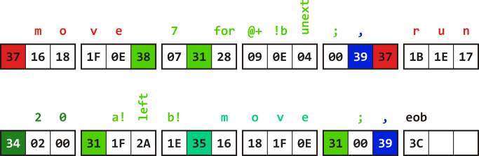
The whole code is displayed on screen as 54 characters (including spaces) but takes only 34 6‑bit symbols in buffer memory.
When the source code is sent from buffer memory to VGA display, it undergoes several conversion steps. First, all tags except for non-printable tags eol and eob are used to set color of the characters that follow. Then tokens are expanded into series of characters. Character codes are incremented by one, so that now code zero is used as a blank character. Finally, each string of characters (name, number or expanded token) is preceded by one space. Position of each space preceding a string is compared with the current cursor position, and when they match a blinking cursor glyph is displayed instead of the space.
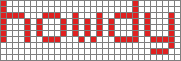
Each row on the screen is composed of 20 scan lines so as to generate 480 scan lines per frame. The same scan line is displayed twice. Thus, characters are actually only 10 pixels high. Characters are defined in 5×7 matrix, which can be shifted two pixels down for characters with descenders. This leaves space between rows one pixel high. An empty column one pixel wide follows each character. The font used has been designed by Greg Bailey many years ago. An example of how characters are displayed in one row is shown here.
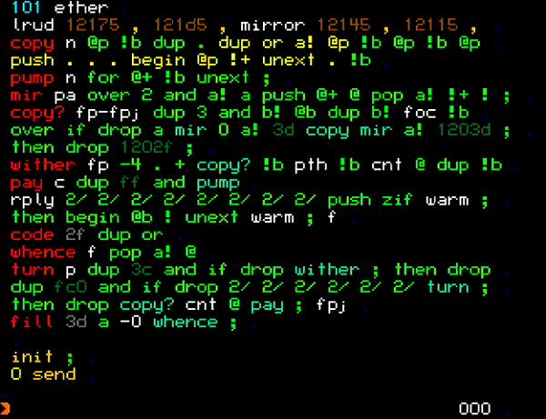
An example of a full screen is shown in the picture below.
Colors and character bitmaps are defined when building etherforth image. Therefore, you can modify both to best suit your display. See source code of Video module.
Keyboard
Input device used by etherforth is a USB keyboard. Upon booting system up and starting USB host controller, the keyboard is initialized and its readiness is signalized with CapsLock LED turned on. I have tested five different keyboard models and all worked as expected, so chances are you can use any keyboard you have. Since etherforth needs only the main alphanumeric section and function keys (no need for cursor keys or numeric pad), you can use a mini keyboard as well. I'm using this model as it has flat keys which allowed me to place colored stickers on function keys. As you may guess, these are used to select tags when editing source code.
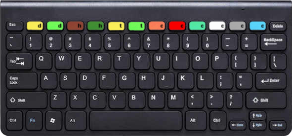
The diagram below shows etherforth keyboard layout. Keys in grey are not used and pressing them has no effect. Alpahumeric keys depict normal (lower left) and shifted (upper left) characters. Right side of the keys shows what tokens these keys generate. Whether you enter a character or a token depends on the current tag selected.
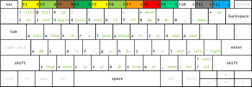
If you can touch type it will take only a short time to learn where each token is located. Before you finish your first application in etherforth you'll know it by heart. You can download this layout as a pdf file here.
Mass storage
Mass storage implemented in etherforth has two levels. The first level represents permanent storage of source code in a MultiMediaCard. The second level is a working copy of data from MMC stored in an external SRAM. Source code in SRAM can be displayed on screen, edited, and compiled. In order to store source code permanently we can write it back from SRAM to MMC. This architecture allows faster access to and manipulation of data in SRAM in comparison with much slower MMC, which is necessary in order to perform these operations in time constraints required by the Video module.
MMC controller implemented in etherforth uses SPI protocol to access raw card sectors. There is no file system implemented. Structure of data stored on disk is simple, and easy to edit with any disk editor software if needed. The space available in MMC is divided into virtual disks, where content of one disk represents the maximum data that can be kept temporarily in SRAM.
Eval board package provided by GreenArrays contains a 2 GB dual voltage MMC card, of which etherforth uses 128 MB to implement 128 virtual disks. Each disk has capacity of 1 MB, of which 910 KB is used for 1‑KB blocks. Each block contains 256 18‑bit words, each word stored as three bytes using only six least significant bits per byte. This accounts for 256 K 16‑bit words of SRAM accessible to the system.
At boot up, the content of DISK 0 is copied into the SRAM. There is a disk command to switch between virtual disks. Whole disk content or individual blocks can be read into SRAM or written back to MMC. This way we can copy content from one disk to another. Although the system can use only a fraction of MMC and SRAM capacity, the available space is sufficient to keep source blocks for 116,480 nodes, i.e. source for more than eight hundred fully programmed GA144 chips. Pretty large space for many etherforth applications!
Interpreter
Functionality of the interpreter is rather limited in comparison with classical Forth. When the system boots up the interpreter becomes active, as is indicated by cursor positioned at the beginning of the bottom line on the screen. It awaits a request to be typed in, which can be composed of numbers (stored on interpreter's stack) and words. Hitting Enter key sends the content of the command line to the interpreter to interpret and execute it. This allows you to invoke editor, compiler, development tools, or to save SRAM content to MMC to name just a few.
Editor
Similarly to colorForth, the editor has two modes: one is navigation mode, where you move cursor around the source code, jump from one block to another, and delete whole words; the second mode is used to enter text. You can easily switch between two modes. Since the navigation mode uses letter keys to move the cursor, similarly as in colorForth, it takes some practice to use this mode smoothly.
The editor also implements shadow blocks. Each even number block (except block zero) can be used as a source block, and a block with number one greater is its shadow block. When in the navigation mode, we can toggle between source and its shadow block by pressing a key. When a source block is copied with copy command, both source and its shadow are copied to the destination. This keeps comments linked to the source. Other than that, shadow blocks are not different from source blocks so if needed, you can keep source code in shadow blocks as well.
Compiler
Compiler reads 6‑bit source code symbols from SRAM, builds a small dictionary, and compiles literals and f18 instructions. It buffers compiled code in 2 adjacent nodes; one is used for image code that is delivered to the target node's RAM, the other for initialization code. Buffering compiled code also allows updating forward references (if, ‑if) and replacing call with jump instruction at the end of definitions (tail recursion). The compiled object code is delivered by an ether message via SERDES line to its destination node in the target chip.
Development tools
To facilitate code development in etherforth we can dump content of RAM and stack of a target node and display it on screen. It is also possible to execute code in the target node from an address we choose, to modify target node's stack content, or to execute any instruction word in a target node's port. There are also means that allow your application to display any text on screen, even repeatedly, thus giving it ablility to provide feedback. Examples of this feature are given in demo applications "Hello World!" and "Big Clock". Even though these tools are rather simple, they make the system a complete development environment.
Before using etherforth
Since etherforth can run on GreenArrays' chips only, first you need appropriate hardware. What exactly is needed is described in detail in hardware section.