
Development board
Current version of etherforth has been developed for GreenArrays' evaluation board EVB001. The system should run on EVB002 too but I haven't tested it yet. It should actually run on any hardware composed of at least two GA144 chips, serial flash memory, SRAM, and USB-to-async interface. One GA144 chip (host) runs the system, the other chip (target) is intended for applications. Target chip does not actually need to be located on the same board. A block diagram of minimal board configuration (equivalent to EVB001) is shown here.
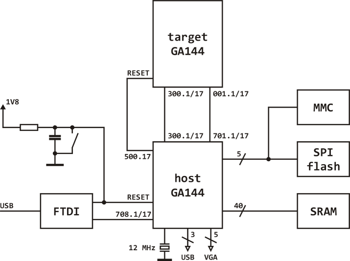
It must be noted that USB-to-async interface (FTDI chip) is needed only to bootload umbilical version of the system, to burn standalone system image into serial flash memory, in order to archive MMC content in a PC, and for system development and testing. Once running, standalone etherforth has no practical use of USB-to-async interface.
Add-ons
Apart from the development board you'll also need some add-ons: a power supply (EVB001 cannot provide all necessary voltages), 12 MHz clock source, and VGA and USB interfaces.
Power supply
EVB001 provides 1.8 V regulated power supply. To assure appropriate levels on HSYNC and VSYNC signals for video display you need 5.0 V power supply as well. It is also needed to provide VBUS for USB. You also need 3.3 V to power voltage level shifter (see below) to be able to communicate over USB data lines with a keyboard. When connected with a PC via USB, you can get 3.3 V power from FTDI USB-to-async interface of EVB001 but you still need to provide 5 volts from an external source.
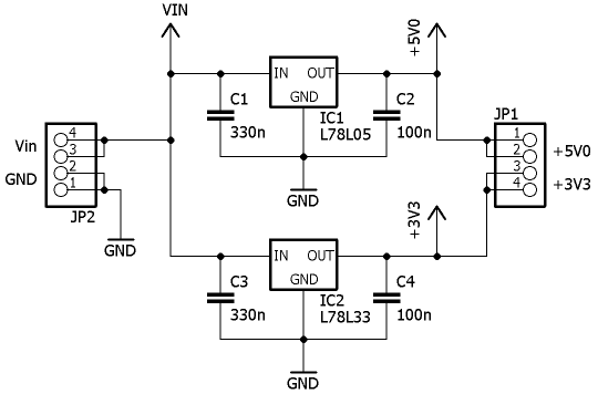
A more elegant solution is to provide both voltages with an external regulator supplied from the same source as the eval board itself. In my system I use 12 V wall wart to power 1.8 V regulator internal to EVB001, as well as a simple module with two regulators: L78L05 for 5.0 V, and L78L33 for 3.3 V supply. Both are rated for 0.1 A output current, which is more than sufficient for the intended use (the keyboard and transistors on HSYNC and VSYNC lines need about 18 mA). Schematics of the regulator is shown below.
Clock source
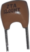
Even if GA144 runs asynchronously, we need a clock source in order to communicate with USB keyboard and synchronize with VGA monitor. For reasons explained in Clock module section we use a 12 MHz ceramic resonator as a clock source instead of a quarz crystal.
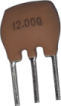
I used a two-lead ceramic resonator placed between host chip pin 417.17 (J21.4) and ground. Keep the leads as short as possible. You can also use a resonator with three connections, which seems to be easier to get. In that case clip the middle lead off as close to the package as possible. Be careful, these leads are very thin and they break off easily. Even if three-lead resonator includes capacitors it works the same as two-leads part.
VGA connector
EVB001 has been designed for one VGA connector. Unfortunately, there are errors in hole pattern placement. I used a straight female PCB mount VGA connector, removed pins not needed, bent the remaining pins a bit, and soldered the connector into PCB. However, some monitors don't like when all GND lines are not actually connected to the ground. That's what happened to me, and I couldn't correct it on EVB001 anymore. Therefore, I had to cut VGA cable and connect ground lines together there.
For that reason I recommend to solder short wires between VGA holes on EVB001 board and pins of VGA connector (use the version for cable, not PCB). This way you can connect all connector pins to their respective holes. Analog RGB outputs from the host chip are connected according to this table:
| from | to | description |
|---|---|---|
| J27.2 | J67.1 | red |
| J27.5 | J67.2 | green |
| J27.7 | J67.3 | blue |
In order to generate 5.0 V HSYNC and VSYNC signals, I used dual NFET transistors Q1 and Q2, intended on eval board as simple serial interface, as voltage level shifters. Make the following connections:
| from | to | description |
|---|---|---|
| J21.3 | J59.2 | 517.17 |
| J58.2 | J67.4 | HSYNC |
| J21.1 | J54.2 | 617.ao |
| J52.2 | J67.5 | VSYNC |
| 5.0 V | J52.4 | power supply |
| 5.0 V | J58.4 | power supply |
Additionally to the connections above you also need to solder a 1k5 resistor between analog output pin 617.ao and ground. This resistor serves as a DAC load.
USB interface and connector
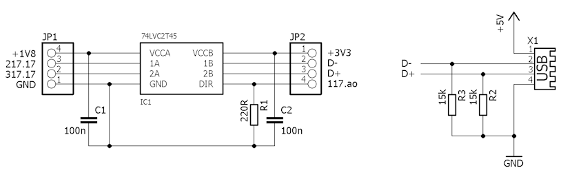
GA144 GPIO pins operate at 1.8V, while USB data lines run at 3.3V. Thus, we need a voltage level converter. What complicates the matter is the fact that data lines are bidirectional, and line drivers must be open collector type, so that USB device (a keyboard) can switch direction when sending a reply. I tried to build the voltage level converter with on‑board TXB0108 circuit, as well as its open collector analog TXS0108 but none worked correctly. Finally, I decided to use bidirectional TI 74LVC2T45, thus avoiding need for an open collector circuit, since line direction is now controlled from GA144 (pin 117.ao). How this works is explained in USB module description. USB interface schematic is shown here.
Peripherals
For mass storage, a dual voltage MMC is needed (part of GreenArrays's eval board package). Unfortunately, you can't use the MMC packed with EVB002. For some reasons unknown to me this card does not work with my MMC controller. I'm working on finding out how to remedy this but for the moment only tested and working correctly is Kingston mobile MMC Dual-Voltage 2GB card.As an input device any USB keyboard will do. An output device can be any monitor with a VGA input capable of 640×480 pixel resolution.