
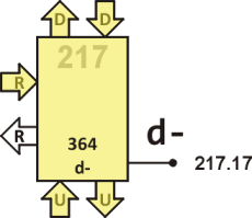
Node 217
This node controls USB D- line (217.17). It also controls USB D+ line by sending code DOWN to node 317, and DIR input of 74LVC2T45DC voltage level shifter by sending code UP to node 117. It is the central point of half duplex communication, i.e. it executes from RIGHT when transmitting, and from UP when receiving.
Source code
send 00 a up a! over ! a! ;
j 03 @p ! .. 12004 +j , 30000 !b 12005 out send ;
k 09 @p ! .. 12006 +k , begin 20000 !b 12005 out send ;
se0 0F @p ! .. 12004 +j , end
idle 12 @p ! .. 12029 idl , 10000 !b 12003 in send ;
atch 18 up a! 12007 atch ! down a! ;
atch? 1D @b -if atch ; then up a! 1200B dtch ! ahead **
ear 23 12027 rx send ---u ;
read 26 -n @p ! @ ; !p ;
nxt 28 read ahead *
inp 2A @p ! .. 12015 sync , read if dup send swap then *
@b send drop send ---u ; then send r--- ;
rest 34 12000 bit 3 for dup ! unext ;
go 38 then ** 10000 !b left a! @ atch r--- ; 3E
init io b! r--- ; 41
5 d 9 r 0 u ether
Definitions
- send
- It is used to write one word to 117 via DOWN without modifying A.
- j
- Set both D+ and D- lines to the J level, and also set DIR out via 117. We cannot use word names from 117 as it is defined later. Thus, we write explicitly call instruction 12005 instead of out.
- k
- Set both D+ and D- lines to the K level, and also set DIR out via 117.
- se0
- Set both D+ and D- low (single ended zero) and DIR out.
Any following call of j, k or se0 is suspended until the previous state has been clocked out in node 317.
- idle
- Set both D+ and D- lines as inputs with low pull down and DIR to in.
- atch
- Call atch in 117 to inform host controller that a device has been/is still attached. Keeps A pointing DOWN, which is its default content.
- atch?
- It is called from 216 after SOF to test whether a device is still attached. If so it calls atch, which sends signal to the controller. Else it calls dtch in 117 to inform controller of detached state and jumps to go, i.e. the reset state of 217.
- ear
- It is called from 216 when we want to start listening to incoming packets. First we start rx in 117 and then execute from UP. Thus, the control of 217 is effectively transfered to 117.
- read
- It executes !p ; at DOWN of 317 and effectively moves contents of its T to stack of node 217.
- nxt
- Read next bit from D+ line and jump ahead to read state of D- line, then send both to node 117. Notice that we don't need to explicitly inform node 317 that the reception is over. It just waits for next word to be executed at its DOWN port and is oblivious to whether it's asked to receive or transmit. When end-of-packet is detected by 117 instead of calling next nxt it lets 217 jump to RIGHT.
- inp
- Start sync in node 317 and read a word. If the word received is zero, in which case node 317 informs that no sync pattern has been detected, just send this zero flag to node 117 and jump to RIGHT, i.e. the reception has failed and it is the end of receive state. Else send a duplicate of the word fetched from node 317 as a non-zero flag to node 117, then read IO (i.e. D- line state) and send both words with double send to node 117. It already knows bit stream is coming (initiated previously with ear). Finally jump to UP waiting for next instructions from node 117. Node 117 may call word nxt.
Words, nxt and inp are used to send bit stream received from USB by 317 and 217 to node 117. When reception of a packet is requested, 117 first calls inp and if sync pattern is detected it starts reading bits with nxt, including bits of sync pattern. It is separated later downstream.
- rest
- It uses bit in 317 to create a four‑bit time pause on the bus. Used when it is needed to settle the bus down to check whether a device is still attached or when changing direction from receive to transmit.
- go
- This is the entry point for this node. It sets D- to weak pull down and suspends reading LEFT waiting for pin 217.17 going high. This indicates attachment of a device. It then calls atch, which sends a message to controller via node's 117 word atch, sets A to DOWN and starts executing from RIGHT.
- init
- Set B, and jump to RIGHT.
Description
As a USB host, this module always starts a transaction by transmitting packets. Therefore, node 217 executes from RIGHT, and jumps to UP only when we expect a reply from a slave device. At any rate it only performs actions upon requests from the host controller implemented in nodes 014 and 015.
Upon boot up, the node suspends executing from RIGHT. When controller node 014 boots up, it sends call instruction to word go, which sets GPIO pin to weak pull down, and suspends the node again until the level on the pin goes high (suspended in fetch from LEFT), which indicates a low-speed device has been attached. Then we call atch to indicate this state to the controller, and we jump to RIGHT, awaiting further commands.
Transmission of a frame starts by controller calling word atch? to test if the device is still attached. When getting affirmative reply via recieve path, controller sends out packets by calling words j, k, se0, and idle. They set appropriate level on D- line (pin 217.17), and call corresponding words in node 317, which sets the right level on D+ line (pin 317.17). Timing of each state is assured by node 317.
When the USB controller expects a reply from a device, it calls word ear, and jumps to UP, so that it can be controlled from node 117. That node then calls inp, which initiates packet reception. It asks node 317 to recieve sync signal, and report either success or timeout; then it recieves data bits with word nxt until the end-of-packet signal. Data bits are sent downstream via recieve path. When the end-of-packet is detected, we inform the controller about this state, and node 217 turns back to transmitter mode by jumping to RIGHT.