
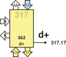
Node 317
This node controls USB D+ line (317.17) and bit timing by reading from UP (signal provided by clock in node 417). It's basic state is suspended executing DOWN. Thus, it is fully under control of node 217.
Source code
21 org k? 0 org
bit 00 15 for @ unext -d-- ;
+j 04 20000 !b bit ;
+k 06 30000 !b bit ;
@bit 09 -n @ @ @ @ @ @ @ @ @b -d-- ;
edge 0D 271 for @ @b -if pop ; then next dup or -d-- -d-- ;
sync 15 edge @bit
j? 17 15 for @ @b - -if @bit k? ; then next - -d-- j? ;
k? 21 15 for @ @b -if @bit j? ; then next -d-- k? ;
idl 29 10000 !b -d-- ; 2C
init up a! io b! ! clock-start idl ; 31
5 d 9 r 1 u ether
Definitions
- bit
- Wait 16 clock ticks, i.e. 667 ns (duration of one bit at 1.5 Mb/s data rate) and jump to DOWN. This is the fundamental bit timer when transmitting to the bus. While bit is running, node 217 is usually suspended trying to execute in DOWN. Thus, both 317 and 217 get timing from bit clock.
- +j
- Set D+ line to the low-speed J level, and wait one bit time before jumping to DOWN.
- +k
- Set D+ line to the low-speed K level, and wait one bit time before jumping to DOWN.
Words +j and +k are all that is needed for transmission.
- @bit
- Wait 8 clock ticks, i.e. half-bit time, then read IO and jump to DOWN. Thus, the state of D+ line is left in T; 20000 corresponds to J state, and 30000 corresponds to K state.
- edge
- Wait 17‑bits time (272 clock ticks) for a rising edge on D+. If it comes, leave the loop and return, else leave zero in T (sync failure flag). Then call DOWN, followed by jump to DOWN.
- sync
- Call edge and if the rising edge is detected continue reading sync bits (see below). If no rising edge is detected in time, let node 217 read zero value from this T, then return to DOWN execution (that's why edge ends with -d-- -d-- ;).
Upon detecting the rising edge on D+ line call @bit (whose value is read by node 217; it already knows that edge has been detected and bit stream would follow) and wait for the next clock tick (suspended in @) and fall through to
- j?
- Wait at max 15 ticks, i.e. we expect to see another edge (a falling one right after sync) within 16 ticks (because we start counting from the middle of the preceding bit this edge should arrive after approximately 8 ticks). Notice that in each pass through the loop we read IO and test if pin is zero (by inverting it and using -if). If so, we are at the edge of this bit and calling @bit gets its value in the middle of the bit. Thus, any discrepancy in transmitter and receiver clocks is corrected, and the code is self-synchronizing with the incoming signal. After this bit is read by 217 (thus leaving word @bit) wait one bit time (suspended in @) and jump to k?. As it is a forward jump the name has already been defined at the beginning of the source code.
- k?
- The same procedure is repeated as in j? but this time we are waiting for a rising edge (no inversion before -if). If a rising edge is detected we jump back to j? at the end of k?.
- idl
- This is the reset entry point and it's also called when transceivers are entering idle state.
- init
- Set A and B, send a dummy clock start signal to node 417, and jump to idl.
Description
After boot up this node sets its GPIO pin to weak pull down (so that the output signal is low but it can be easily overdriven), and jumps to DOWN. Words defined here are executed only upon requests recieved via DOWN port. On the other hand, execution of words in this node is clocked by node 417 via UP port. Consequently, if node 217 requests execution of two words in succession, the first one is executed immediately but the second word starts only when the first one has finished. This way, both node 317 and 217 are clocked by node 417.
This node, as well as node 217 functions in both directions. In the output mode node 217 calls either +j or +k, to set the GPIO pin low or high, respectively. Both words set GPIO pin level and jump to bit, which waits 16 clock pulses from node 417, i.e. 667 ns or one bit time in low-speed USB.
When the USB module changes direction into the input mode, it first have to sync with incoming signal. To this end, node 217 calls word sync, which waits for a rising edge on D+, which must come within ~11 µs, i.e. 17-bits time, otherwise this node reports timeout.
Detecting a rising edge on D+ line, we fall through to word @bit, which waits a half-bit time, and reads D+ line level. Then we enter into an endless loop made of words j? and k?, in which we read D+ line level every 667 ns, and resynchronize this timing on each edge detected.
Notice that when we read D+ line level, either by @bit, j? or k?, we leave the value read in T, and jump to DOWN, so that it's up to node 217 to read the value from our stack with code executed in DOWN port, or to leave it there and stop reading D+ line.
Auto synchronization is based on fact that if no edge is detected within 16-bits time (in both j? and k?), i.e. after we leave the loop, the value of the last IO reading is left in T to be read by node 217, and after that, waiting one bit time (suspended in @) we jump back to the beginning of the same word. In other words, recieving the same state for several bits, there is no edge we could use for resynchronization, and errors in timing may accumulate. However, due to bit stuffing it lasts for six-bits time at maximum, because an edge must arrive at the latest after this time. The maximum acceptable clock error is thus half-bit time in five bits, i.e. about 10%.
The @ after @bit in sync, j? and k? is here due to timing constrains; we need to be sure that code executed between two consecutive fetches from UP is less than one clock tick, i.e. 41.6 ns.