USB module
USB module provides communication between a keyboard and the system. It detects when a USB keyboard has been attached or detached, initializes a newly attached keyboard, reads and decodes key scan codes and translates them into etherforth symbols and control actions.
Low-speed USB module is an autonomous part of the system. Upon boot up it checks whether a USB keyboard is attached. If not it waits till keyboard attachment. When a keyboard is attached, it starts initialization procedure, which makes the keyboard communicate in boot protocol. Upon initialization the module periodically requests a report from the keyboard, processes the report, and in case a new key has been detected it sends etherforth character code to node 011.
Since the USB module is independent, it can be replaced by other keyboard controllers, for instance a PS/2 keyboard could be attached with use of PS/2 controller as described in GreenArrays' application note AN009 Attaching a PS/2 Keyboard.
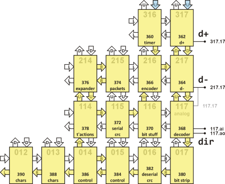
The USB module is composed of several blocks. Timer is in node 316, transceivers are in nodes 317 and 217, transmit path runs through nodes 115, 116, and 216, and receive path through nodes 117, 017, and 016. These nodes form a Serial Interface Engine (SIE). Keyboard controller is implemented in nodes 014 and 015, description of USB packets and transactions for communication with the keyboard in boot protocol are in nodes 114, 214, and 215, and character decoder is implemented in nodes 013 and 012. Clock signal is provided by Clock module via UP ports of nodes 316 and 317.
Transceiver nodes 317 and 217 control USB data lines D+ and D-, respectively. When transmitting, these two nodes generate data line states (J, K, SE0, and IDLE) as requested by controller via transmit path. Transmitted data are clocked out with signal generated by Clock module. During reception, these two nodes synchronize with clock signal recovered from incoming data, they read D+ and D- line states, and send them to the controller via receive path. Node 217 is also responsible for detection of a device being attached and detached.
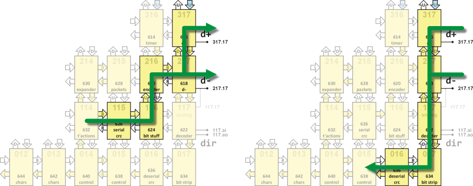
Transmit path is compsed of three nodes. Node 115 receives a stream of data bytes, serializes the data and calculates CRC. Node 116 performs bit stuffing. Node 216 then encodes the bit stream into J and K states by calling appropriate code in transceiver nodes.
Receive path is similarly built from three nodes. Node 117 decodes J and K states into bits, node 017 removes stuffing bits, and node 016 deserializes bit stream, calculates CRC, and performs error detection. Node 117 is also used to switch direction of voltage level shifter based on direction of USB packets.
Data transmit and receive paths are shown in the schemes below.
USB communication is based on transactions, which in turn are composed of different packets. Templates of those packets are stored in a compressed form in node 215. Node 214 expands data stored in node 215 into packets, and those are combined in node 114 into transactions, and transmitted as instructed by a controller.
The controller is implemented in nodes 015 and 014. It waits till there is a keyboard attached. This is signalized from node 217 via receive path. Upon keyboard attachment, the controller initializes the keyboard by sending appropriate packets, and if successful, it starts requesting periodically a report from the keyboard. It then processes the reports received and, should a pressed key be detected, it passes its scan code to character decoder. Non recognized keys and combinations of keys are ignored.
Character decoder reads individual key scan codes and converts them into etherforth character set and control codes, which are sent to node 011 of the Editor module. The codes are buffered in a one-character buffer. Thus, if a character is not read by node 011 before another character is received from the keyboard, the former is discarded. This ensures that USB module can run independently of the rest of the system.
A detailed description of the USB module can be found in my Forth Day 2019 video presentation and slides.