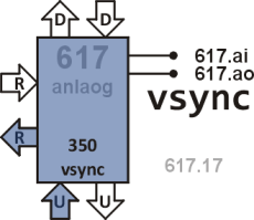
Node 617
This node generates vertical sync signal. It also passes clock signal to node 616.
Source code
ticks 00 n for @ !b unext ;
lines 02 n for 255 ticks next ;
-sig 07 n io b! !b right b! ;
go 0B 12 lines -sig 1 lines -sig 29 lines 479 lines go ; 16
init up a! 155 AA over over
over over over over over over -sig go ; 1F
4 d 9 r 3 u ether
Definitions
- ticks
- Count n+1 clock pulses while sending pulses to RIGHT.
- lines
- Count n+1 lines, where each line lasts for 256 ticks.
- -sig
- Toggle voltage level on analog output pin. Two consecutive calls to -sig generate a negative vertical sync pulse.
- go
- Generate 13 blank lines with VSYNC high, then 2 blank lines with VSYNC low, and 30 blank lines with VSYNC high again. Then generate 480 image lines and repeat the whole pattern.
- init
- Set register A, fill stack with alternating 155 AA values, set pin 617.ao high, and jump to go.
Description
Generation of VSYNC signal is based on 8 Mpulses/s clock rate coming from node 517. One scan line is defined as 256 clock pulses so its duration is exactly 32 µs. It is slightly longer than what corresponds to standard VGA so the frame refresh rate is ~59.5 Hz.
This node generates a negative VSYNC pulse for each scan line with duration of 0.06 ms, i.e. two scan lines. The front porch is set to 13 scan lines (0.41 ms), and back porch to 30 scan lines (0.95 ms). It is possible to change slightly width of the pulse and length of both porches in order to adjust timing to a particular monitor but the total number of blanking lines must be kept the same, i.e. 45 lines.
VSYNC signal is generated on node's analog output pin. In order to work properly a load resistor has to be placed between the pin and the ground (see Hardware section).
Apart from VSYNC signal generation this node also passes character clock signal to node 616.