
Floorplan
Programming GA144 chip is not an ordinary experience. Code written for GA144 is by nature asynchronous, parallel, usually spread over several nodes, and relying on cooperation of nodes involved. To write anything than just a trivial one‑node code, it's a good practice to start with floorplan drawing.
The whole etherforth system takes 137 nodes of the host chip, including 22 ether nodes used to pass messages between system modules. It is therefore recommended to study the code in a top-down fashion, starting from its floorplan, understanding function of individual modules, and then dive into source code of individual nodes.
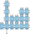
The system floorplan is shown in the picture below. Nodes of the same color belong to a single module. The image is clickable, i.e. clicking on a module opens an introductory page of that module. From there you can get to source code of an individual node just by clicking on the node. There you can move between nodes by clicking on ports (colored arrows around nodes) or you can get back to the module page by clicking on the node itself. There is a high‑resolution version of the system floorplan in pdf downloadable here. A short description of each system module is given below the floorplan image.
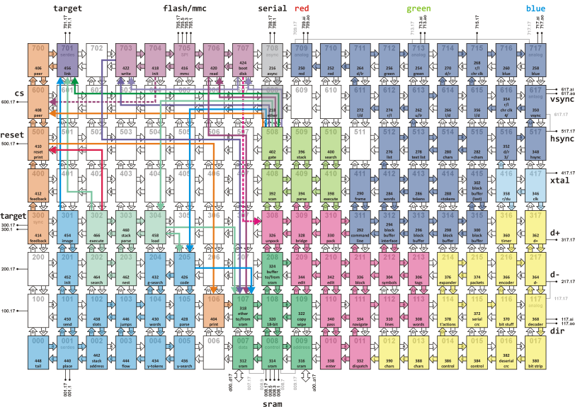
Modules
Modules are more or less self‑contained parts of the system. Modules can communicate with each other either via ports of neighboring nodes or using ether messages. That's why all "unused" nodes (white color in the image above) are not empty; they remain loaded with ether. Ether paths used by the system are depicted as colored arrows, with an arrowhead pointing to the destination node.
Clock module

Clock module uses a ceramic resonator attached to GPIO pin 417.17 to generate 12 MHz signal, which is distributed to video and USB modules.
USB module
A USB keyboard is used as input device that allows interaction with the system. The USB module takes care of recognizing a keyboard has been attached to the system, it initializes the keyboard, reads key scan codes sent by the keyboard, and translates them into codes recognized by etherforth.
The module uses GPIO pins 317.17 and 217.17 as data lines connected to D+ and D- USB lines, respectively. An analog pin 117.ao is used to control direction of 74LVC2T45 voltage level shifter on data lines, explained in the hardware section.
Video module
An output device of the system is an ordinary VGA monitor having resolution of at least 640×480 pixels. The video module uses several nodes as a video buffer. Its content is periodically read and displayed on the screen. Information stored in the buffer is encoded as characters, tokens, and tags in order to keep it compact. Details are given in Video section of etherforth system description.
The content of the video buffer has to be expanded and decomposed into individual color pixels on its way throught the module nodes, until it reaches analog nodes in the top row, where RGB signals are generated. Other nodes generate appropriate horizontal and vertical synchronization signals, all in sync with signal provided by the Clock module. The video buffer is loaded with content of one block from SRAM, and its content can be stored back. It can also be manipulated by Editor module.
Apart from displaying video buffer content the module also displays a command line as the bottom row in the screen. The command line is used to enter commands for Interpreter module, which can access its content and interpret commands entered by the user.
SRAM module

This module enables communication with the external SRAM. It provides three access nodes that allow ether messages to write to/read from SRAM, facilitate access of Video, Editor, and Interpreter modules to SRAM content, and implement copying and erasing of whole blocks. The module performs conversion between 18‑bit etherforth words and 16‑bit wide SRAM cells. The bottom row nodes implement drivers and timing for data, control, and address SRAM lines.
Editor module
Editor module enables creating and modification of source code stored in blocks. Editor recieves characters and control codes from USB module. The codes are dispatched either to navigation functions or editor functions depending on the mode the editor is currently in.
Navigation enables cursor positioning within the currently displayed block or movement between blocks. Editor then provides means to enter and modify text in a block. This module also allows entering commands in the command line and sending them to Interpreter module for processing.
Interpreter module

Interpreter waits for a command to be entered into the command line and sent for processing. When a command is recognized the Interpreter initiates appropriate action either directly in neighboring modules or using ether messages. It notifies user whether the action has been performed successfully or the command could not be recognized.
MMC module

MMC module communicates with the external data storage - MultiMediaCard. Upon reset, it initializes the card into SPI mode. Then, it copies the content of the virtual disk 0 to SRAM. This module enables to write content of blocks from SRAM to MMC and back, and also controls the access to virtual disks on MMC.
Compiler module
Compiler module recieves a request from Interpreter or Loader module to compile source code from a particular block. It clears its dictionary and image memory, then parses the source and compiles the code. Finally, it delivers the code via Link module to the target chip.
Loader module

Loader receives requests from Interpreter module. Its function is to parse and process load blocks. Load block is used to reset the target chip, set up ether there, and compile source code for all nodes that an application needs. It does so by calling Compiler module for each block of source code.
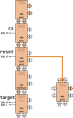
Link module

This module is used to communicate with the target chip during compilation. It is also used when content of a target node's memory or its stack is inspected or modified with debug tools.
Utilities module
This module provides debug tools for the system. It also allows an application running in the target chip to access system's display and give graphical feedback.
Asynchronous link module

Asynchronous link to a PC is not necessary in the standalone system, and only needed for umbilical system upload. It is nevertheless used by colorForth tools for instance to backup and/or restore data from/to MMC. It also provides a back door into the system for further development and testing.